

Electronic systems for renewable energy sources, home automation
|
|
S-CONNECTS-CONNECT is our new software protocol for sharing I/O devices. This protocol makes it possible to share the input and output devices of our devices via the Ethernet network (or WIFI) and also via the existing wireless architecture (SC-Gateway, SC-Router, sockets). 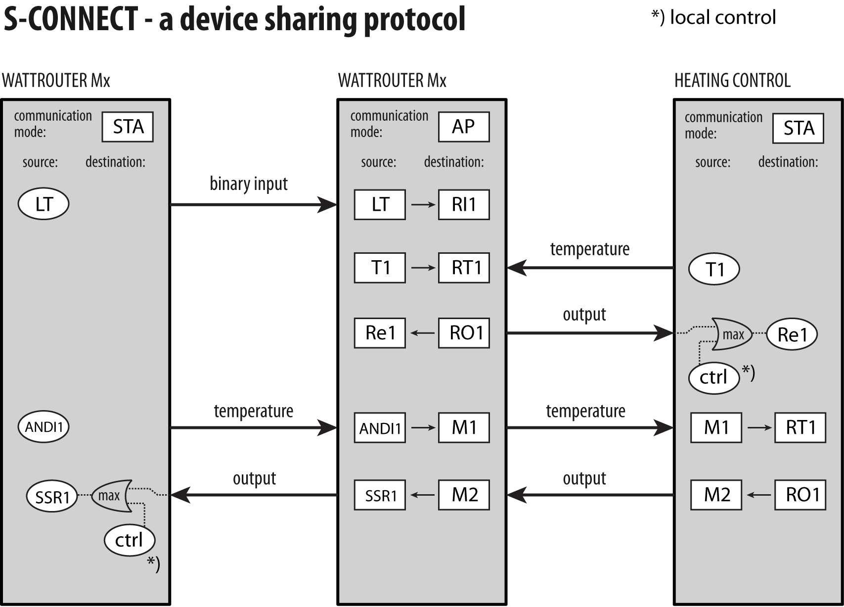 Example of connecting WATTrouter M and Mx devicesThe procedure for connecting two or more devices via the S-CONNECT protocol is described in the relevant instructions, (for example here in chapters "S-CONNECT Protocol Description' and 'S-Connect Tab'). In practice, it is most common to connect two or more Wattrouter M/Mx controllers in order to expand the number of outputs, or remote sharing of binary input states, temperatures, etc. The general principle in this case is that the Wattrouter Mx that is measuring (let's call it the master wattrouter) will be set as an Access Point (AP), and all other Wattrouter M/Mx (let's call them as slave wattrouters) will be stations (STAs). The main wattrouter therefore has a current sensing module connected, the slave wattrouters are only separate regulators. In all slave wattrouters, it is necessary to set the communication mode to "station (STA)" in the S-Connect tab. Nothing else is set here, everything else is set on the master wattrouter. In the master wattrouter on the S-Connect tab, we set the communication mode to "access point (AP)" and then pair the slave wattrouters with it according to the instructions, see the chapter "Pairing stations to the access point". Example of pairing the slave WATTrouter M to the master WATTrouter Mx: 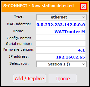 Then, again in the S-Connect tab, we will map remote physical devices to local logical devices that are named RO (from English "remote output"), RI (remote input), RT (remote temperature), etc. In the master wattrouter, this gives us access to the physical devices (outputs, inputs, temperatures, etc.) in the slave wattrouters. We add a new mapping with the "Add entry" button and fill in all the columns in the table accordingly. After that, by default, we write the configuration to the controller with the "Save" button, as with any other change to the controller settings. Example of device mapping of slave WATTrouter M to master WATTrouter Mx: 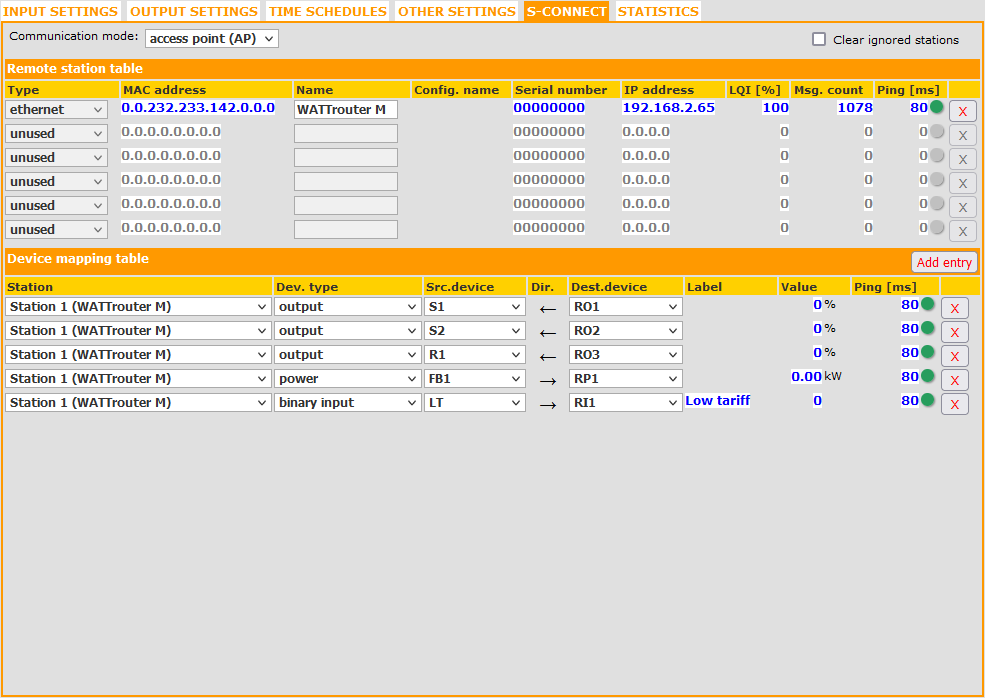 In this example, we gain access in the master WATTrouter Mx to the physical devices of the slave WATTrouter M, namely the outputs S1, S2, R1, the power input FB1 and the low tariff input LT. We can further work with these devices in the master wattrouter, just as if they were available directly on it, using the ROx, RIx, RTx, etc., which are logical devices created for this purpose in the master wattrouter. For example, we can switch the remote outputs of the slave wattrouter from the master wattrouter: 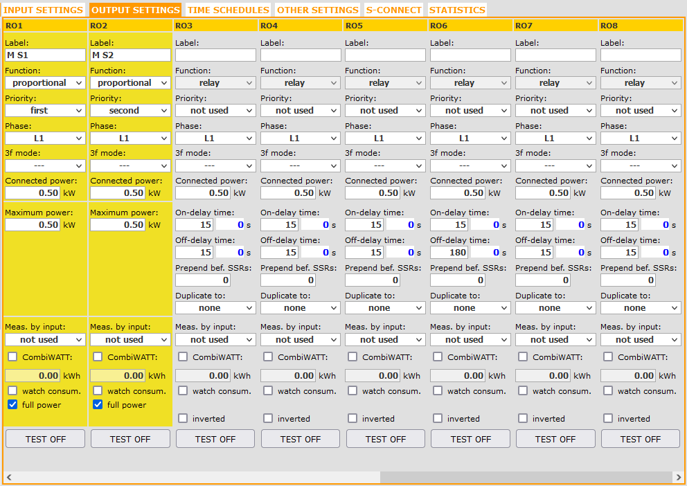 Note: Using the S-CONNECT protocol, the required function for switching the output is also transmitted, i.e. relay, proportional regulation and PWM. The accumulated RTT (roundtrip time) of the remote device (marked on the S-Connect tab with the term Ping) is also transmitted, which the master wattrouter will use to determine the traffic delay and adjust the constants of the PID controllers used for output switching. Or we can use a low tariff signal in the master wattrouter, which is connected to the slave wattrouter: 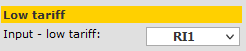 We can use this remote signal for example in time schedules on the master wattrouter: 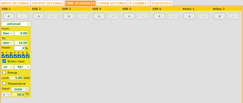 Similarly, in the case of two Mx WATTrouters, we can also map temperature sharing, i.e. D/Q1 -> RT1 and then use the temperature sensor connected to the slave wattrouter in the time schedule of the master wattrouter: The protocol is symmetric. In general, once the master and slave wattrouters are paired, not only can the slave wattrouter's devices be used on the master wattrouter, but also vice versa (if that makes sense). So it is possible to map devices both on the master and on the slave wattrouter. The Ethernet version of the protocol uses TCP port 50160 for data exchange and UDP port 50160 for manual device pairing and UDP port 50161 for automatic device pairing. The protocol can deal with possible disconnection of slave wattrouters as well, e.g. due to a network error. All these devices will be disabled, which is indicated by a red "S-Connect: device error" icon on the master wattrouter. The respective RO outputs and schedules with the associated RI and RT remote inputs will cease to work. For security reasons, in such a case, the physical outputs on slave wattrouters will be disconnected within 30 seconds. This error state is reversible, i.e. once the slave wattrouters are connected back to the master, the respective devices will start working again. Integration information for OEMsThe protocol description is not publicly available because the protocol is closed. If you are an OEM device manufacturer and would like to integrate the protocol into your products, you can ask us for a detailed description. This requires signing an NDA with us. After signing the NDA, we will provide you with a detailed description of this protocol in English. We will also provide you with a sample passive station project (ANSI-C project for Cortex-M3 architecture), which however requires specific test hardware (a LPC176x development board from NXP). We will also provide you with a sample passive station program for Windows OS (Winsock2), which does not require any specific hardware and runs on Windows OS. We will provide these examples by granting you access to the given repository on the Github platform, so you will automatically have access to any updates and new versions of the protocol. Upon request, we can also lend you a test device. If you are interested in integrating the protocol into your devices, then contact us. |