

Electronic systems for renewable energy sources, home automation
|
|
WATTrouter FAQOn this page you can find answers to most common questions about WATTrouter and self-consumption in general. WATTrouter application according to the PV and inverter typeWe support only traditional grid-tied PV plants with classic DC/AC inverter, running parallel with a 230VAC/50 Hz grid, where electricity is typically measured with bidirectional (4-quadrant) meter. WATTrouter cannot be used in island systems with dedicated island inverters and in hybrid systems where the inverter has a disabled energy export to the grid. Moreover, WATTrouter self-consumption management cannot be combined with any other management system, which might be for example built into inverter etc. Yes, and it is the primary purpose of the WATTrouter. With this type of PV, there are almost always situations where energy surpluses flow into the grid, and it is useful to consume them at the production site. WATTrouter can be used with any classic grid-tied installations with a bidirectional billing electricity meter. You install in the standard way shown here (image above). Yes, but only conditionally. With this type of PV, energy surpluses into the grid may occur, provided that they are enabled in the inverter of this PV. Then the WATTrouter can be installed, but in almost every case it must be installed in the specific way shown here (image below). More detailed information about usability with a hybrid inverter can be found here. No, because this type of PV does not generate any energy surpluses into the grid. Such PV is either completely separated from the grid, or the grid is used only as a backup source, when there is a rectifier at the grid input of the PV inverter. Such PV then works basically as a UPS station with extended options for charging the battery, which can usually be realized either from the grid or from PV panels, or even from a power station. When operating such a PV plant, there may be a need to accumulate electricity from the PV panels at a time when they are still supplying electricity, but the battery is fully charged and at the same time there is little consumption on the AC output of the inverter. Unfortunately, the WATTrouter cannot be used for this either, as there is no generally acceptable way to determine the amount of power available to provide such regulation. Some manufacturers of competing regulators similar to the WATTrouter try to apply different alternative ways to find out the available amount of this energy, for example by detecting the state of charge of the battery. However, we consider these methods to be very risky and generally unusable due to the fact that the regulatory functions of the inverter itself are directly interfered with here. It is fundamentally valid here that the possible switching of other consumers in order to obtain the maximum amount of energy from the PV panels in this type of power plant must always be part of the inverter itself and no external regulator or switching element can be used for this! The above also applies to hybrid PV plants, where it is not possible to enable energy surpluses into the grid. WATTrouter is compatible with any inverter of classic design, which runs parallel to the 230V / 50Hz electrical network and supplies power to this network. It is also possible to use hybrid inverters, which provide electrical storage using a built-in or external battery and which meet the above conditions. Hybrid inverters use their own energy management to control battery charging and discharging. Usually, the inverter uses its own electricity meter (smart meter), which performs a similar function as the WATTrouter measuring module. When combining this inverter with a WATTrouter, care must be taken to verify that these 2 control loops do not interact in a bad way. The issue of combining a hybrid inverter with a WATTrouter can be summarized in the following modes:
It is obvious that WATTrouter can therefore be combined with a hybrid inverter without any problems, except when the inverter covers the house consumption from the battery. So how the positive feedback during battery discharge mode can be avoided?
Economic aspects of the WATTrouter installationIt always depends on the distribution of consumption time and PV-production time. If you mainly consume electricity from grid at night (heatings, hot water preparation, etc.) then yes, WATTrouter should be able to help you. But if there is steady consumption at daytime (many computers, machines etc.) it might be difficult for WATTrouter to find any surplus energy to "route" it somewhere else. In such cases there is no suitable load to connect to WATTrouter, perhaps except for expensive battery equipment. If you use gas or oil heating you can consider to buy a high-capacity water tank where WATTrouter will be able to put the surplus energy. You can use accumulated hot water from this tank even for more days when the sun is not shining. WATTrouter controllers have 6/8 outputs. It is possible to connect up to 6/8 loads. But if you have neither swimming pool to heat and filter its water, nor wet rooms to dry in summer, nor an air-conditioner, just sell the surplus energy as usual. WATTrouter will pay itself in 2-4 years horizon even with the boiler (this depends on local regulations). If you have a hybrid PV plant with a large battery, then a certain part of the generated electricity will be used to charge the battery and the payback of the WATTrouter installation will be extended by this. It then depends on how much higher the average PV production is, especially in the summer season, than the amount required to charge the battery. I.e. how much energy the WATTrouter will be able to redirect to any heating elements. WATTrouter installationThe recommended maximum distance is 2m. In practice, the cable can be extended up to 20m, then the measurement accuracy is reduced by approx. 0.1% per 1m. This longer cable must be consistently shielded according to the information provided in the user manual. For longer distances, we already recommend connecting multiple controllers using the S-CONNECT protocol. The recommended maximum distance is 10m. A supply longer than 2m must be consistently shielded according to the information provided in the instructions. For longer distances, we recommend either extending the power circuit to the connected load or connecting multiple controllers using the S-CONNECT protocol. The recommended maximum distance for external current transformers is 2m, for other input devices 10m. The supply must be consistently shielded according to the information given in the instructions. For longer distances, we already recommend connecting multiple controllers using the S-CONNECT protocol. The recommended maximum distance is 50m, or the total length of the D/Q bus should not exceed this limit. The supply must be consistently shielded according to the information given in the instructions. For longer distances, we already recommend connecting multiple controllers using the S-CONNECT protocol. This parameter varies according to the type of current sensing module or the type of current transformers:
Standalone pull on current transformers 53484 (50A) and 53638 (100A) have two leads distinguished by colors (typically a black and yellow cable). A different color indicates the winding sense of the transformer, which should be the same for all CTs. If you connect 3 CTs as a replacement for the three-phase current sensing module WT02/10 or WT03/11, then you connect all wires of one color (usually black) from all 3 transformers to the terminal Y (for WATTrouter Mx/Mx 100A) or GND (for any other models), and you connect the wires of the other color (usually yellow) to the individual inputs of IL1-3. Connection example for the WATTrouter Mx controller: 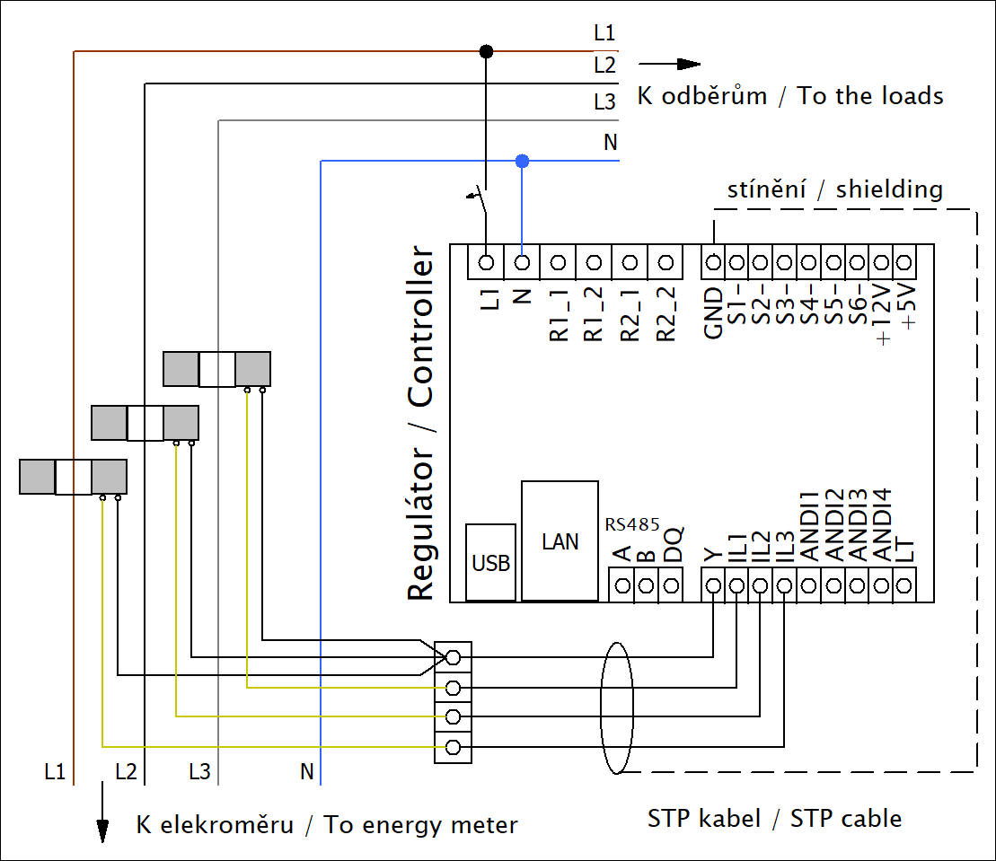 During this connection, do not forget to observe the same direction of the current flow through the primary phase conductors for all 3 transformers, so that the current flow directions can be selected in the WATTrouter settings in the same way for all inputs IL1-3. Therefore, wire all three transformers to the three-phase supply in the same direction, so that the outputs of the transformer always point to the same side. If the CT cables are short, use shielded STP or similar cable as indicated on the picture above. Because installation is easier in many cases. There is often not enough place in existing house wirings and the module is small enough to fit into it. Regulator can be placed even 20 meters away from the module (with appropriate shielded cable). There is also possible to connect more modules to one regulator, where the secondary currents of the modules just add to each other (see user manual). There has to be always wire between regulator and the module, wireless communication is not possible. Connection of meters and sensors to the inputsThey should have optically isolated impulse output marked as S0 output, according to the DIN EN 43864. Typically they have an open collector output (NPN transistor + some shunt resistor). Suitable types can be found among Carlo Gavazzi EM series, Applied Meters AMT series, Maneler 99 series, etc. Some WATTrouter models allow the current range to be increased by adding additional current transformers (CTs). For this purpose, use types of any design (we don't recommend clip-on types) with a primary current corresponding to the value of the main circuit breaker (eg 200A) and a secondary current of 5A. Choose the power according to the cross-section and length of the secondary line and the maximum secondary current. Accuracy class 1 or better. Thread the secondary cables of the CT through the original WATTrouter current sensing module according to the instructions for the given type of WATTrouter. Never connect them directly to the regulator, or the regulator will be irreparably destroyed! Then set the Ratio for external CT items in the Input settings tab accordingly, again according to the instructions for the given type of WATTrouter. Sensors containing original chips DS18B20 or DS18S20 from Maxim Integrated Products (originally Dallas Semiconductors). For recommended types see here. We warn against very cheap sensors sold typically at various Chinese eshops. These sensors may not contain the original chips and may not work with WATTrouter. An example was the MK00241 DS18B20 compatible temperature probe (not anymore on the market), which did not comply with the original chip specifications for the communication bus voltage levels and did not work with the WATTrouter and Heating Control devices. NTC type sensors with 10kOhm at 25°C (B25/85=3977) or PT1000 sensors. For recommended types see here. The low tariff (LT) logic in our devices assumes there is always an external signal that informs about LT presence. And can be connected to the controller via its LT input, as shown in the user manual. This is always the case in CZ, SK, and other countries. In case you don’t have such signal and you only know the LT switching times, then there are 3 options:
Note: It is strongly recommended to connect the LT input with the switching signal from the electricity meter switchboard. This way you will not have to constantly check whether your electricity provider has changed these times, and, moreover, in case of accidental time changes in the controller, the low tariff functions will remain working. Connection of loads to the outputsYes. If there is no electronic control in that device, just heating element with mechanic (or electromechanic) thermal fuse, then you can connect this to a triac or SSR output and take benefits from the accurate proportional control. Otherwise you have to use relay (or proportional output in relay mode). If this load is connected to a separated line in your house (not just wall outlet) then it is basically possible. WATTrouter can optimize the time when the freezer can run and with CombiWATT mode it can switch it even if there is little surplus energy. But we don't recommend this. To keep the quality of stored meals the temperature should vary as little as possible. Additionally, in case of malfunction of WATTrouter due to some unpredictable events the freezer contents might melt down. Yes but you have to observe existing connection to some dedicated control system. The WATTrouter output can be connected in series with the existing system's switching element or in parallel. Use serial connection if you don't want to heat more than necessary (activate CombiWATT in that case to allow the dedicated heating regulator to switch on even if there is no surplus energy). Use parallel connection if you want both systems to be run independently. Polarity and correctness of phase wire must be observed to avoid short circuit here! Yes but this element has to be connected in Y mode and the neutral line must be also used. It means this element must be used such as 3 independent heating elements connected between each phase wire and neutral wire. Yes but only using a relay output. For electricity meters configured to evaluate each phase separately this might not be good idea because that load can be switched on even if there is not enough surplus energy in other phase wires. Yes. The same applies as for boilers / immersion heaters. No electronic control - you can connect to triac or SSR and benefit the accurate proportional control. Otherwise connect to relay. Yes, it is possible if the air conditioner manufacturer supports this connection, i.e. the air conditioner has the necessary input available. Operation of the air conditioner together with the WATTrouter is possible in the following ways:
According to our own experience, we recommend mode according to point 3. Always contact the air conditioner supplier who will suggest the most suitable type of air conditioning according to your needs. Caution: We definitely do not recommend controlling the air conditioner with the WATTrouter by simply switching the power supply of the air conditioner with the contactor without the consent of the manufacturer/supplier of the air conditioner! If it is switched/disconnected like this often, there is a general risk of damage to the compressor or other components of the air conditioner! Therefore, always consult the air conditioner manufacturer first about such switching! Yes, it is possible if the heat pump manufacturer supports this connection, i.e. the heat pump has the necessary input available. For example, Fujitsu and Mitsubishi inverter units have that option through a 0-10VDC control signal, with appropriate accessories (control boards). Then, WATTrouter output is set to PWM mode and connected through a PWM/0-10V interface to the control board of the inverter unit.  Accessories according the picture:
WATTrouter configuration: Any SSR output is set to PWM mode and additional parameters like Connected power, PWM-I, Minimum power and time delay must be configured:
Important notice: As mentioned above, AC or heat pump inverter units react on input power changes very slowly, almost 2 orders slower than regular heating elements, so it is necessary to count with higher consumption from grid during the day. This is not just because of the Delay parameter. Inverter units can increase or decrease their input power for some time when their internal control algorithm requires this (e.g. needs of higher lubrication, pressure balancing etc.). Even that, proportional regulation of inverter units brings more effective usage of surplus energy than in cases we switch them to full power in ON/OFF mode. Moreover, thanks to the COP factor, surplus energy gets consumed much more effectively on these inverter units than on regular heating elements. This depends on many circumstances. Mainly on nominal power of your PV system, what electricity meter is installed and how the heat pump is going to be used. In case you have a 4-quadrant electricity meter, which measures each phase separately (this is the case in CZ), than it is suitable to use three one phase inverters (e.g. split A/C units). WATTrouter Mx and ECO can control all 3 of them with PWM mode, WATTrouter M just 2 of them. In case of 4-quadrant meters which take vector sum from all phases or regular power meters we can take advantage of the "sum of all phases" control mode. Then you can use and control even one three phase AC unit by one external output from WATTrouter. We always set nominal power input of the three phase AC unit as Connected power and activate the "sum of all phases" control mode. The big advantage of the proportional regulation of inverter units is the compatibility with any kind of electricity meter. You do not need to deal with situations where the electricity meter counts surplus energy as consumption from grid. This situation may occur only at the moment once inverter unit does not react fast enough on sudden increase of surplus power. According to our latest tests, these states will usually endure couple minutes only. Yes you can. We will mark this load with the letter A. So that the relay does not oscillate during regulation, i.e. does not constantly switch on and off the connected load A, it is necessary to set the highest possible power of the load A in the "Connected power" configuration field. We will set the 1st priority for the relay output. Then the relay output will be switched on only if the available PV surplus exceeds this maximum consumption of the load A, and will be switched off if the available PV surplus falls below the power consumption of the load A. If no other load is connected, then in this switching mode there is a noticeable waste of available PV surpluses. To prevent this from happening, and to make optimal use of all available surpluses, we must use another load, which we will mark with the letter B. This load must be thermal (purely ohmic) and have a power consumption greater than or equal to the maximum power consumption of the load A. We will connect the load B to a triac or SSR output in proportional control mode. This time, for the relay output with the load A, we will set the 2nd priority and its configuration field "Prepend" to the value 1. For the triac/SSR output with the load B, we will set the 1st priority. In this case, when the PV surplus power increases, energy is first stored in heat load B connected to the triac/SSR output, and as soon as the connected power of the load A is reached on the relay, load A is switched on. The triac/SSR immediately and automatically reduces the power so that both loads A and B are switched on and optimally cover the available surpluses. The load A will be disconnected automatically when the power of the load B drops to zero and the PV surplus drops to such an extent that load A would draw energy from the grid. The above description might be difficult to understand for you. If so, please contact us with your questions. Yes, but the charger must have externally controllable charging power (eg. through a 0-10VDC signal, then WATTrouter PWM mode should be used) or at least be externally switchable (relay function applicable only in this case). WATTrouter does not control discharging of batteries, here different control system has to be used. Currently, everything is usually handled by a hybrid inverter that manages the charging and discharging of the battery itself. See point Which inverters is WATTrouter compatible with? Especially notes on hybrid inverters. Yes, but the vehicle charger (or wallbox) must have externally controllable charging power (eg. through a 0-10 VDC signal, then WATTrouter PWM mode should be usable) or at least be externally switchable (relay function applicable only in this case). For variable charging through the 0-10 VDC signal the electric vehicle can be charged with variable power, i.e. only with the PV power that is currently available. It is known that all electric vehicles have lowest charging current set to 6 A and their charging current can be increased to 10, 16, 20 or 32 A according to IEC 61851. For that, our control mode built originally for heat pumps can be used. Ask for a wallbox that has 0-10V control input and is (or can be) programmed as follows:
This setting allows charging with the maximum charging current when the 0-10V control signal is disconnected from the wallbox/charger. Note: We cooperate with several Czech companies that provide such control signal and corresponding settings in their charging cables or wallboxes. Of course you might find a wallbox with different settings but in that case you might have to set WATTrouter differently. We consider the above settings as a standard. If you have such vehicle charger (wallbox) then connect its 0-10V control input to any SSR output of WATTrouter:
Then select the SSR output in WATTconfig as follows (for 1-phase charger, assuming you use control mode set to "Sum of all phases"):
For 3-phase charger, set Minimum power to 3x 1,4 kW = 4,2 kW (as 6 A limit is per phase). Connected and Maximum power 3x 3,7 kW ~ 11 kW (for 3x 16A max. charging current). Again we assume you're using "Sum of all phases" control mode. Note: It is not possible to use surplus energy below 6 A (0-1,4 kW) for vehicle charging (when using only PV power for that). Because of the 6A minimum charging current. If you want to use this surplus power you need another load, eg. a heating (eg. 1,5 kW). Connect it to another SSR output with second priority. This load will be active until there is 1,4 kW surplus power availabe to start vehicle charging. WATTrouter featuresWATTrouter will never provide absolutely zero excess energy at any setting, because the reaction to transient events always takes some time for the built-in PID controllers. The zero energy export cannot be achieved even when using appliances with an inverter/converter (e.g. inverter heat pumps), proportionally controlled according to surpluses in PWM mode. However, zero export can be very close, as shown by the operation of our reference installation. The percentage of self-consumption here reaches more than 99%. They can't. WATTrouter contains only classic relays or solid state switches. Routing from one phase to another would require a relatively technically complicated and expensive device based on an inverter. In case of the "sum of all phases" control mode, this does not need to be solved, in case of the "each phase independently" control mode, energy surpluses must be consumed only on those phases where they are present, ie. to which the outputs of the PV inverters are connected. They can't. WATTrouter does not and will not support such management for security reasons. Quickly switching a single-phase appliance to another phase could damage some appliances. Yes, it is possible. Use a relay output in the last priority and either disconnect the inverter entirely on its AC side or use the inverter input which is used to disable inverter (the inverter must support this). However, we do not recommend this method, as we install the PV plant in order to produce. It is therefore much better to add suitable appliances (e.g. air conditioning, pool heating) that can accommodate all PV production even on hot summer days. Because the WATTrouter does not measure the current flowing through the outputs, or connected appliances, and from the measured power on the individual phases it is generally not possible to recognize the disconnection (or reconnection) of an appliance connected to the output of the WATTrouter. In order for the WATTrouter to detect such disconnection of the connected load, it is necessary to measure the current flowing through the load directly. Only our latest Mx model supports this measurement, for a maximum of 4 outputs. For this, it is necessary to purchase the external current transformers, which are compatible with the WATTrouter, or another measuring module. Connect them to the ANDI inputs and use them to sense the current in the circuit of the connected load. The relevant ANDI inputs must also be set correctly in the WATTconfig application, see the user manual. The above measurement slightly improves the parameters of the regulation by the fact that the physically disconnected outputs are not included in it and only the actually measured delivered energy is included in the statistics of the respective outputs. For all older models (CWx, ECO, M) or even the Mx type without the above-mentioned additional measurement, in the event of physical disconnection of the connected appliance, the corresponding output will be fully excited, i.e. permanently switched on, when the WATTrouter detects surpluses from the PV plant. Because of this condition, the negative feedback necessary for the regulation of this appliance is broken. The daily energy counters of these outputs then show the expected power supplied to the appliance, which, of course, does not agree with the actual state. The counters will then show higher (sometimes significantly higher) values than the energy actually supplied to the connected appliance. It is therefore advisable to have enough space (a large storage tank or a pool to heat or similar) where energy can be stored without frequent disconnection of the appliance by the thermostat. The reasons may be:
Usually the WATTrouter measures slightly smaller surpluses and consumption than reality, but in some cases even bigger values. Differences of up to 10% are possible. It is caused by the following influences:
For these reasons, there may be a long-term discrepancy between the values in the statistics and the data from the electricity meter. This is also why we explicitly state that the values in the statistics are indicative only. The statistics are therefore only a certain guide for the user, they were added to all relevant types of Wattrouters only later in terms of development. Measurement and control algorithms were created much earlier. Some improvement can still be achieved by experimenting with the current measurement calibration in the WATTrouter settings. Calibration can be performed for all measuring inputs (IL...) by changing the value of the Ratio of external CTs, e.g. to 10:9, if the WATTrouter usually measures smaller power values than is the reality. Or the other way around, e.g. 9:10, if it measures greater power values than in reality. This is a normal operating condition. The causes differ according to the type of PV system (this description is only valid for connections prescribed or recommended by us):
In general, if the WATTrouter correctly measures the consumption (power of the appliances connected to it), the device is ok and will work properly. It does not directly support it, because this control requires proper EMI filters. The resulting high-frequency interference can be very significant even with the use of the EMI filters. There are solid state relays on the market designed for instantaneous switching (and therefore phase power control) that are controlled by a 0-10V signal. It is therefore possible to connect them to SSR outputs set to PWM mode via a PWM/0-10V converter (or directly to the WATTrouter Mx 0-10V outputs). We have not yet verified this solution ourselves, so we cannot give more detailed information about suitable SSRs and necessary EMI filters. WATTrouter configuration, data connection optionsYes. USB connection is the basic connection option for all models and the connection is made either with the included USB cable or any other suitable USB cable. The USB connection driver must be installed on the PC. The driver is installed automatically for Windows 8 and later if the PC is connected to the Internet at the same time. Alternatively, the driver can be downloaded from this page and installed manually. If the driver is successfully installed, the USB Serial Port (COMxx) item is displayed in the Windows OS device manager in the Ports (COM and LPT) column (this item is only displayed in the device manager when the USB cable from the WATTrouter is connected). Then just select the correct port in the WATTconfig software (in the USB/COM driver configuration window). If the driver cannot be installed, or the installation fails, even repeatedly, contact an IT and computer professional who should be able to use diagnostic tools to troubleshoot the problem. If the connection does not work even after installing the driver correctly, please contact our technical support. Yes. For models with an Ethernet interface (M, Mx), any router or switch is used and the connection is made with an ordinary UTP cable - typically CAT5e. In order for the connection to work correctly, it is necessary to set the IP address of the WATTrouter correctly so that it corresponds to the network mask of the local network, or activate the DHCP protocol according to the instructions. Direct cable connection with a PC is also possible without the use of a router/switch. The connection is made again with an ordinary UTP cable (it is not necessary to use a crossover cable). It is then necessary to manually set the IP address in the PC so that it corresponds to the network mask in the WATTrouter (ie if the IP of the WATTrouter is e.g. 192.168.2.200 and the mask is 255.255.255.0, we set for example 192.168.2.1 in the PC and of course the same mask). If everything is set correctly, then it is enough to choose the IP address of the WATTrouter in the WATTconfig software (in the LAN/UDP Interface Driver Settings window). The procedure is more complicated for models without this interface (CWx, ECO). It is necessary to use an Ethernet-USB converter, which ensures a remote connection of a USB device via an Ethernet interface. For monitoring of these types, you can use the type Silex SX-3000GB tested by us or its newer replacement Silex SX-DS-510. This converter provides basic connection in a home or business network. According to information from our customers, cheaper Mikrotik devices with RouterOS and a USB port can also be used, but they require professional settings - only for RouterOS experts, see https://wiki.mikrotik.com/wiki/Serial_Port_Usage. If the connection does not work, contact an IT and network professional who should be able to fix the problem. Yes, although the WIFI connection is not directly supported. For models with an Ethernet interface (M, Mx), a secondary WIFI router with the Bridge with AP function is used (e.g. the TP-Link WR743ND router supports this). For models with a USB interface (CWx and ECO), this requires a USB extension via WIFI, e.g. Silex SX-DS-520AN. If everything is set correctly, then just select the IP address of the WATTrouter in the WATTconfig software (in the LAN/UDP driver configuration window) and you should be able to connect. If the connection is not working, contact an IT and network professional who should be able to fix the problem. Since there is usually a weak signal strength directly in the switchboard, place the respective WIFI device outside the switchboard (if possible). Also keep in mind that a network cable connection will always be the most reliable, so we recommend to install an Ethernet cable into the switchboard rather than using WIFI.
No, Bluetooth is not supported in any of our devices.
For models with an Ethernet interface (M, Mx) yes. But it is necessary to have a fixed public IPv4 and to configure NAT in the router. Public fixed IPv4 usually is a paid service (monthly fees). We recommend using a fixed public IPv4, but it is not required. If getting a fixed public IPv4 is expensive, a dynamic public IPv4 that doesn't change very often will do the job. Some operators provide a dynamic public IPv4 by default, or is assigned for historical reasons. This IP then changes at various times (e.g. every time there is a power outage). Therefore, you must always verify the connection with such a dynamic IP on your installation. Recently, many operators provide only non-public IPv4 as part of their standard services, thereby solving the global shortage of these addresses (IPv6, which was originally supposed to solve this, was designed really badly, so almost no one uses it anyway). With this non-public IPv4, it is not possible to connect directly to the controller from the Internet, and then it is necessary to solve it, for example, via a VPN. Various instructions for this can be found again on the Internet. However, even a VPN solution is usually not without monthly fees, so it is best to actually order your own fixed IPv4. An alternative to fixed IPv4 is to connect to a supported cloud service. This option is only available for WATTrouter Mx. An example is connecting to the Sophistio cloud service. Another alternative is to display the web interface in a browser on an always-on home server, which can be, for example, a Raspberry PI minicomputer. You can then connect to this minicomputer from the Internet using some remote management service for computers (eg Anydesk). In this way, however, you cannot use the controller's built-in protocols (XML, MODBUS) from the outside, so you can't even connect to the controller using a mobile application. WATTrouter devices only support IPv4. If you don't have public IPv4, but only IPv6, then the NAT configuration may be more complicated. Connection from the Internet may also not be possible at all, or may require the use of a different router, or additional hardware. Always contact computer networking experts if you are unsure. Devices with an Ethernet interface allow two types of connection - via the web interface using the HTTP protocol and then via the WATTconfig application using a non-public special protocol based on UDP. Each configuration change is password protected, and for each type of connection, the port on which the device will listen can be set. Access to the device is therefore sufficiently secured due to the nature and function of the device. A higher level of security (with the HTTPS protocol used for internet banking, etc.) is not possible due to the hardware equipment of the device. If you want to be sure that unauthorized access to the device will not be made from the outside, never share your password with anyone and make all settings changes only within the local network. Yes. WATTconfig desktop applications are available for Windows OS for all models, for ECO, M and Mx models Linux and MACOS OS applications are available either. All desktop applications only work for the IBM compatible 64-bit x86-64 hardware platform (or older versions of applications for the 32-bit x86 platform). These applications are not (and will not be) available for other operating systems and hardware platforms, and for these devices it is only possible to configure the device using the built-in web interface. If you still want to use the WATTconfig desktop applications on other platforms, then you need to use virtualization or an emulator. For example, if you're using a Windows ARM computer, then you'll follow this link. In a Linux environment on an ARM platform, you use Wine (in which you run a Windows application) or Box64 (in which you run a Linux application). However, all these emulators may have a problem with the USB drivers and in general with the USB connection to the controller. For Ethernet models, this can be done using a web interface and/or special mobile applications. Mobile apps are only available for the most popular mobile OSes Android and iOS. Apps for other OSes are not available and will not be available. For these devices, you can only configure the device via built-in web interface. This is a normal condition if it is a sporadic occurrence of these or similar errors: 1.10.23 10:00:36: [Warning] SOLAR controls communication log says: Log error: Unable to read data from LAN device (IP:192.168.2.200,port:50000)![ /p] In the case of the Ethernet interface, the controller is only able to process a certain amount of incoming messages (packets) per time unit. Error rates increase when the Ethernet interface is loaded with additional traffic. If, for example, S-CONNECT or MODBUS TCP communication is active, then errors will be even more frequent. The WATTconfig log can be used, among other things, as a visual indication of whether the communication with the device still works well (about 15 errors per minute) or is already overloaded. The increased occurrence of errors may also be related to the local network overload. It also depends on the number of broadcast type packets in the local network, which the controller has to receive and process. Some PC services/programs broadcast them periodically and often. It is advisable to use, for example, the program Wireshark and possibly disable those services that "spam" these packets into the local network. For possible optimization of local network operation, contact an IT and network expert. In the case of the USB interface, errors can indicate communication interference, especially if a long USB cable is used. If the occurrence of errors is very frequent without an obvious cause, and the communication is obviously overloaded or even broken, the relevant USB/Ethernet communication interface may be damaged. In this case, please contact our technical support. Yes, you can. For the newer Mx and ECO models, we sell the expansion modules for wireless communication - SC_Gateway, SC_Router modules and wireless switching sockets. They are made by another Czech company named ENcontrol s.r.o. Wireless sockets made by the Czech company ENcontrol s.r.o. can currently switch the load in a relay mode, according to the user manual. The proportional control mode for heateres or heat pumps must be solved using an additional WATTrouter ECO regulator equipped with the SC-Router module. Wireless sockets and the SC-Router module work within approximately 20 m from the WATTrouter equipped with the SC-Gateway interface. So they will typically work within the small house. However, there must not be thick walls or a reinforced concrete ceiling or other structural elements preventing signal propagation between the two elements. The range is therefore similar to that of a regular WIFI router. In cases where it is not possible to connect to the controller in a given location, it is necessary to purchase a radio repeater from the manufacturer ENcontrol s.r.o., or another wireless element (e.g. another wireless socket). Each wireless element also serves as a radio repeater for other wireless elements, so the more of these wireless elements we use in a given object, the wider the radio signal coverage area. We always place the repeater so that it is reliably within reach of the WATTrouter with the SC-Gateway module and the endpoint wireless element, i.e. somewhere in between. We do not supply the radio repeater, see here. for technical and ordering info.Note: Some wireless systems have a greater range, but these usually operate at lower frequencies (868 MHz, etc.) and are more powerful. The wireless system of the manufacturer ENcontrol operates at a frequency of 2.4 GHz with a very low radiation power to reduce the electromagnetic pollution to the maximum extent possible. WATTrouter is designed without display. One reason is to keep low price of this device. Another reason is the way this controller gets configured. Expecially WATTrouter models with the Ethernet interface are usually connected to the Ethernet network and can be monitored and configured from PC, smartphone, tablet etc. Function is indicated with several LEDs and the computer based setup is very comfortable. Protocol support depends on the specific WATTrouter model. The following protocols are supported:
Yes we have. For example, see our reference installation, where you will see the connection of two controllers (WATTrouter Mx and Heating Control) directly in action. Also see the protocol information page, which shows an example of connecting the WATTrouter Mx and WATTrouter M controllers. Yes we have. Examples of communication are given directly in the user manual for the given device as part of the description of this communication. Yes we have. See the protocol information page for an example of connecting to Modbus Poll. No. We have our own S-CONNECT protocol, which is perfectly suited for these purposes. We plan to create a hardware bridge to connect devices communicating via other IoT protocols. Yes. If you have a superior system available that has an ethernet interface or RS485 and supports the relevant communication protocol (e.g. MODBUS), you can connect WATTrouter models that also have Ethernet interface, or RS485 interface. This is not possible for models without Ethernet and RS485 interface (WATTrouter CWx and ECO). Yes, but only for models with Ethernet interface or RS485, i.e. WATTrouter M and Mx. The connection is implemented using the MODBUS protocol, see here for more details. This is not possible for models without Ethernet and RS485 interface (WATTrouter CWx and ECO). No, and there are no such plans even for a few specific types of inverters in the future. WATTrouter works independently of the type of inverter. Some manufacturers of competing controllers similar to the WATTrouter try to implement data communication with specific types of inverters, e.g. to find out production data or battery state of charge. We do not support this philosophy mainly because there are a large number of manufacturers and types of inverters. Each manufacturer uses a different communication protocol, or in the case of the MODBUS communication protocol, then a different map of registers. In practice, it is not possible to support all manufacturers and types. Even with one specific type of inverter, it may be difficult to maintain such a data connection in the future, if, for example, the inverter firmware is updated and the communication protocol changes. Cloud ServicesCurrently, only WATTrouter Mx supports connecting to cloud services. The following cloud services are supported:
The Sophistio cloud service provides advanced options for managing your photovoltaic power plants and energy flows in your objects (houses, companies). It provides several modules (systems) for controlling photovoltaic power plants, appliances, energy sharing, etc. Using this cloud service, you can manage the energy flows of your objects with such algorithms that the wattrouter as a local control system can never achieve. You can also watch or control your WATTrouter Mx device remotely, without the need of fixed IP address. At present (August 2024) the service is Czech only. We will release an English version of the setup guide when the service is available internationally. You may refer to the Czech version though. Compatibility with electricity metersThe WATTrouter can in any case be connected in such a way that it is compatible with any bidirectional electricity meter of the classic design that complies with the EN 62053 standard. Yes. Normally, bidirectional electricity meters measure the balance (sum) of the power from all three phases. The 'sum of all phases' control mode is then used in the WATTrouter settings (see the user manual). However, in some countries (CZ, SK) a special measurement mode is used, where the bidirectional electricity meter evaluates each phase separately. With these electricity meters, production and consumption from all phases are not added up, and individual phase conductors are assessed separately. This means, a state is possible when you supply electricity to one phase and take it from the other phase at the same moment. If your electricity meter has this configuration, it is necessary to set the control mode 'each phase separately' (again see the user manual), otherwise the WATTrouter will not work correctly. Unfortunately, in this mode it is not possible to regulate self-consumption in any way for phase wires, where no inverters are connected. Therefore it is advisable to connect powerful appliances to the phase wires where inverters are connected to. It is necessary to pay attention to the contemporaneity of connected appliances and loads and which appliances are mainly switched on during the day and which are more likely to be switched on in the evening. If you live in a country where bidirectional meters might be configured differently (ie. either for 'sum of all phases' or 'each phase separately'), you should check the meter settings. The configuration of your electricity meter should be communicated to you by your electricity provider. If he is not able to do this, it can be tested for a short time, for example, by taking electricity mainly from 2 phases and supplying it to the third phase. Based on the production statistics (data from the inverter) and the counters in the electricity meter, it is then easy to find out whether the electricity meter sums up the production/consumption from all phases or assesses each phase separately. The WATTrouter proportional control of triacs and SSRs works on the principle of skipping and switching full half-waves of the mains voltage. That's why only zero cross triacs or SSRs are directly supported. This switching, in addition to the fundamental frequency, produces mainly harmonics close to this frequency (subharmonics). The switching does not produce a DC component. Higher harmonics are in accordance with EN 61000-3-2. A classic electricity meter that complies with the EN 62053 standard must meet the requirements of section 8.2 for accuracy tests in the presence of harmonic current components. To comply, electricity meters usually contain specialized circuits that provide the measurement, digitization and calculation of instantaneous values of currents and voltages from all three phases and from these they calculate effective values of active power, among other values. For the indicators of production or consumption, the effective values of active power are authoritative. Considering that for the calculation of the steady-state effective value of the active power, approx. 900ms is needed, such control can be used to control the power of the thermal loads. Here, even a relatively large number of half-waves can be skipped. Therefore, even at low power levels switched by the triac, or SSR, there is no phenomenon that the electricity meter measures the consumption from the grid when the half-waves are switched on and, on the contrary, the flow into the grid when the half-waves are not switched on. As in almost every technical aspect, there is also development in the electrical energy measurement. It is clear from the previous paragraphs that the switching modes, which operate on the principle of rapid changes of consumption and production, that they make use of a benevolent electricity measurement as performed by the existing types of bidirectional meters. In principle, static (digital) electricity meters have so far worked as old mechanical (disc) electricity meters, where the disk stood still or vibrated weakly during the steady state of WATTrouter proportional control. In other words, this meter basically measured wrong values, because the disc also did not react quickly enough to the rapid alternation of production and consumption. Existing static electricity meters work similarly to the old disc electricity meters. In the future, the innovation of bidirectional electricity meters cannot be ruled out, so they will be able to react more quickly to these changes and can more accurately measure rapid changes in the energy flow. This has not yet happened. This would be a fundamental change in the principle of electricity measurement, however. So, what to do if there is such innovation of bidirectional meters? It is clear that the WATTrouters will no longer be able to use the proportional control mode. It will not be possible to use the above described phase power control either, because this control also works on the rapid alternation of production and consumption. These control modes may lose their effectiveness completely or only partially. It will therefore be necessary to accomodate to the switching only in the relay mode or in the mode of controlling suitable appliances with a 0-10V signal, i.e. appliances with a built-in inverter. In relay mode, the ideal choice would be the cascade switching of several appliances with small nominal power consumption, e.g. heating elements with a power consumption of up to 500W. SSRs with zero cross switching will also be suitable for this, because they will ensure that the appliance is switched on and off at zero mains voltage with reduced inrush currents, and moreover the switching will not be audible. This depends on the type of such electricity meter. The old mechanical (disc) meter usually works without problems, the disc vibrates weakly or stops during WATTrouter regulation. The new electronic (static) electricity meters probably will count any surpluses to the grid as if they were consumption from the grid. Such meters should not be used together with any classic (on-grid) PV installation. Feedback to the power grid and other appliancesIf the WATTrouter is connected in accordance with the installation and operating instructions, then only rapid changes in the mains voltage, the flicker, can be observed. Flicker is caused by the switching of power loads connected to triacs and SSRs. The power of the heat appliance is modulated by skipping mains sine half-waves, and this causes rapid changes in the mains voltage. A very similar method is also used in every electronically controlled heat appliance (e.g. instant flow water heaters). The control used in the WATTrouter complies with the strict criteria of the EN 61000-3-2 and EN 61000-3-3 standards, and assuming reasonable use and correct settings of the WATTrouter, this negative effect on the power grid is minimal. See below for measures to reduce flicker. If the WATTrouter is connected in accordance with the installation and operating instructions, sensitive people may only experience fast flashing light bulbs and fluorescent lights. This is caused by rapid changes in voltage in the network, i.e. the flicker as described above. See below for measures to reduce flicker. If you are a person sensitive to disturbing light phenomena (flicker), despite the compliance of the control with the EN 61000-3-3 standard, you may feel the consequences of the flicker during the proportional regulation of the power loads connected to the triac/SSR outputs. The regulation suppresses the manifestations of flicker to the maximum extent possible, it is physically impossible to completely remove them. Considering that the controller smoothly regulates only during the day, when it is usually not lit, these phenomena obviously have a marginal effect (after dark, only the CombiWATT mode can be active or the time schedule, where the full switching of the triac/SSR can be set, which makes the flicker completely eliminated). General recommendations for minimizing flicker when the proportional control mode is set are:
If excessive long-term flicker (marked as Plt) is detected by your electricity provider (it is measured according to EN 50160), then it is necessary to make the following adjustments, some of which are identical to the above:
The calculation of the maximum power depending on the network impedance can be done according to the following table:
Note: The values shown in this table are based on the measurement of long-term flicker Plt with our regulation according to EN 61000-3-3. In practice, when measuring the quality of the network according to EN 50160, other influences and the switching of other appliances, not only those connected to the Wattrouter, are also manifested. These are also counted in the resulting long-term flicker. It is therefore recommended to further reduce the specified maximum levels to 3/4, i.e. in the case of a normalized impedance of 0.47Ω, use a maximum load of 1.5kW. Sales informationPlease refer to the table on this page. |